REDAC
A REDAC is the rack-level analog computer built from multiple iREDACs stacked one above another in a 19-inch server rack. Each iREDAC is one complete stack level with its own backplane, mREDAC modules, frontplanes, coverplane interfaces, routing resources, synchronization paths, and controller interfaces.
The current REDAC rack uses four populated iREDAC levels, numbered 0..3. The rack layout also supports a configuration with five iREDAC levels when the reserved expansion/service space is populated accordingly.
As a larger system option, one or more additional REDAC racks can also be connected to expand the available system resources.
At system level, the REDAC provides:
- A shared 19-inch rack structure for multiple iREDAC stack levels.
- Rack-level power, networking and super controller.
- A LAN path for communicating with the controller interfaces of the installed mREDACs.
- A super controller that acts as the rack-level configuration gateway for REDAC computations.
- Stacked iREDAC resources that can be configured together for larger analog computations.
Architecture Overview
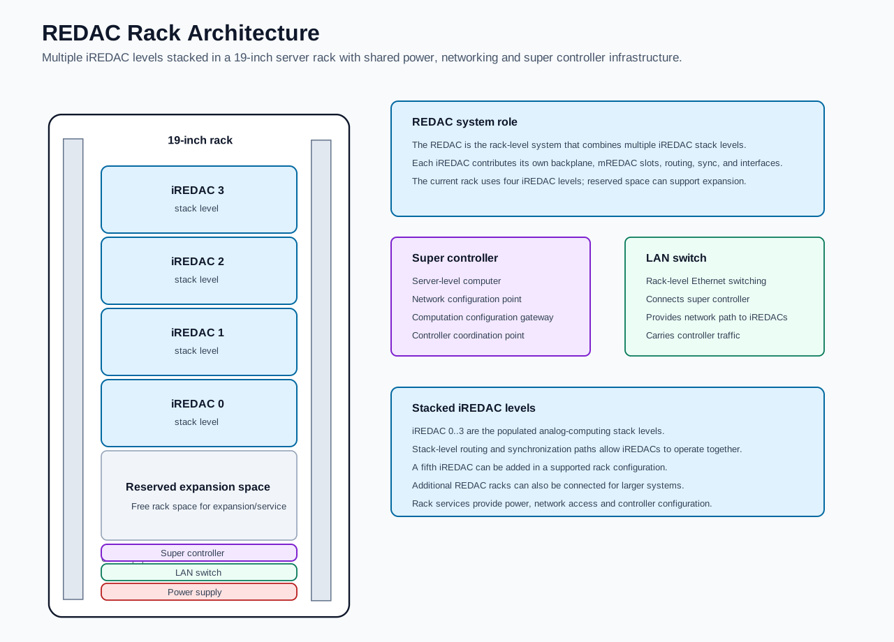
The diagram shows the current four-iREDAC rack configuration and the surrounding rack-level infrastructure. The iREDAC pages describe the internal composition of each iREDAC stack level.
Rack Layout
The current REDAC rack is organized from bottom to top as follows:
| Position | Role |
|---|---|
| Power supply | Rack-level power source. |
| LAN switch | Rack-level Ethernet switching for controller communication. |
| Super controller | Server-level computer for network setup and REDAC configuration. |
| Reserved expansion/service space | Free rack space for expansion or service access. |
iREDAC 0 |
First populated iREDAC stack level. |
iREDAC 1 |
Second populated iREDAC stack level. |
iREDAC 2 |
Third populated iREDAC stack level. |
iREDAC 3 |
Fourth populated iREDAC stack level. |
| Top blank space | Top-side blank spacing. |
A five-iREDAC configuration adds another iREDAC level in a supported rack arrangement, typically using part of the reserved expansion/service space.
Super Controller
The super controller is a server-level computer in the REDAC rack. It is the main rack-level configuration gateway and coordination point.
The super controller is responsible for:
- Network configuration for the REDAC rack.
- Configuration access to the mREDAC controller interfaces installed across the iREDACs.
- Distributing computation configurations to the REDAC system.
- Coordinating the configuration flow from software to the controller interfaces that operate the analog hardware.
In normal operation, computation descriptions are prepared by software and sent through the super controller. The super controller then uses the rack network path to reach the controller interfaces on the installed mREDACs. Those controllers configure the iREDAC-level and mREDAC-level hardware resources needed for the requested computation.
LAN Switch
The LAN switch provides the rack-level Ethernet network path. It connects the super controller to the network interfaces of the installed iREDACs and mREDAC controllers.
This network path carries:
- Controller discovery.
- Configuration transfer.
- Status and diagnostic communication.
- Runtime communication needed by the configured REDAC setup.
The LAN switch is therefore the central Ethernet distribution point of the rack.
iREDAC Stack Levels
The populated REDAC currently contains four iREDAC stack levels:
iREDAC 0iREDAC 1iREDAC 2iREDAC 3
Each iREDAC provides up to seven mREDAC positions. A fully populated four-iREDAC REDAC therefore provides up to 28 mREDAC module positions. A five-iREDAC configuration provides up to 35 mREDAC module positions.
The iREDAC stack levels provide the scalable analog computing resources of the REDAC. Each level contributes local computation modules, backplane routing, synchronization, and external interface paths. Stacking iREDACs extends the available routing and synchronization scope beyond one iREDAC level.
Configuration Flow
A typical REDAC configuration flow is:
- The computation is prepared in software.
- The configuration is sent to the super controller.
- The super controller communicates through the LAN switch to the installed mREDAC controller interfaces.
- The mREDAC controllers apply the required configuration to their local blocks and routing resources.
- The iREDAC backplanes and stacked-iREDAC paths provide the selected routing and synchronization between configured resources.
- The REDAC executes the configured analog computation using the installed mREDAC computation blocks.
Programming with pybrid
In pybrid, the REDAC is represented by the controller.computer entity model initialized from the discovered hardware specification. The stacked iREDAC levels are addressed with the stack field in a Loc, and the mREDAC positions within each iREDAC are addressed with the carrier field.
The main addressing concepts are:
stackidentifies the iREDAC level, such as0..3in the current four-iREDAC rack.carrieridentifies the mREDAC slot inside one iREDAC, using0..6.clusteridentifies the cluster inside one mREDAC, using0..2.ididentifies the lane inside the cluster.
If a fifth iREDAC level is populated and discovered, it would normally appear as the next stack ID, stack=4. The usable stack IDs and routes depend on the discovered hardware topology and available routing resources.
Example locations on two adjacent iREDAC stack levels are:
from pybrid.redac.entities import Loc

src = Loc.new_lane(stack=0, carrier=0, cluster=0, id=20)
dst = Loc.new_lane(stack=1, carrier=2, cluster=1, id=20)
Here, the source is on iREDAC 0 and the destination is on adjacent iREDAC 1. The route can be requested on the REDAC router:
This updates the in-memory REDAC model, including the relevant mREDAC T-Block and iREDAC backplane T-Block BPL configuration objects when the required resources are available. The configuration becomes active on the hardware after it is sent through a controller session:
For real hardware configuration, use carriers discovered or loaded with valid location metadata and with the relevant routing blocks present in the model. If the router context is incomplete, pybrid may operate on placeholder routing objects rather than changing the serialized configuration for a physical T-Block or T-Block BPL.
The same routing constraints apply at REDAC level as at iREDAC level:
carrieruses0..6for the seven mREDAC slots inside one iREDAC.clusteruses0..2for the three clusters inside one mREDAC.- Backplane-capable routed lanes use mREDAC lane IDs
8..31. - Source and destination lane IDs must match for routed paths.
- Lanes
0..7are local same-cluster lanes.
The LAN path reaches the controllers; the analog routing APIs operate on the discovered carriers, clusters, lanes, local T-Blocks, and backplane T-Block BPL resources.
Routes between non-adjacent iREDAC stack levels require supported intermediate topology and routing resources. They should be described as multi-step or topology-dependent routes rather than as a direct adjacent-stack route.
Related Documents
- iREDAC describes one complete iREDAC stack level.
- Backplane describes the iREDAC carrier and interconnect board.
- mREDAC describes the module installed in each iREDAC backplane slot.
- T-Block BPL describes backplane-level topology routing.
- List of Blocks gives an overview of the REDAC hardware blocks.