Backplane
The backplane is the iREDAC carrier board. It provides the shared analog-routing, digital-control, synchronization, networking, and identification infrastructure into which up to seven mREDAC modules are plugged.
The backplane provides the higher-level interconnect that lets the installed mREDACs work together as one iREDAC. It carries the shared routing, control, synchronization, networking, and identification paths needed to combine multiple mREDAC modules into one system level and, where connected, exchange routed topology lanes with neighboring iREDACs.
An iREDAC backplane contains:
- 7 mREDAC slots, numbered
0..6. - Plug-in T-Block BPL / T-Block BPL modules for backplane-level topology routing.
- Digital backplane logic for distributing control and selection signals.
- LAN/Ethernet paths for the mREDAC controller interfaces.
- Identification logic for board and slot-related readout.
- Synchronization wiring and selection logic for coordinating mREDACs within one iREDAC and, when stacked, multiple iREDACs.
Architecture Overview
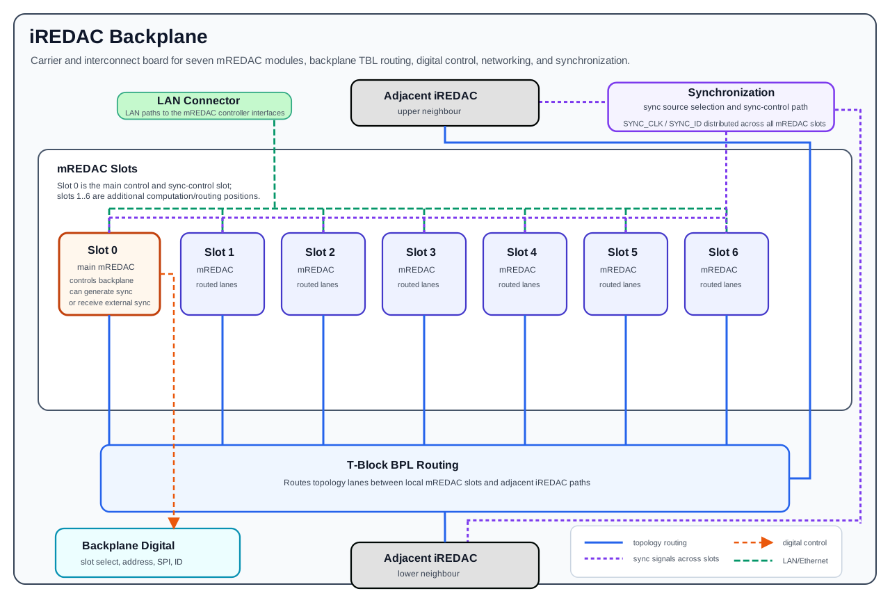
The diagram shows the functional relationships between the mREDAC slots, the T-Block BPL routing blocks, Slot 0 mREDAC role, LAN/Ethernet controller paths, synchronization paths, and adjacent iREDAC links.
mREDAC Slots
The backplane provides seven mREDAC positions:
- Slot
0is the main slot. - Slots
1..6are additional mREDAC positions controlled through the backplane infrastructure. - Each plugged mREDAC contributes its local clusters, local T-Block, Ctrl-Block, and frontplane-facing resources.
- The backplane connects the mREDAC-level routed topology lanes to the T-Block BPL routing system.
Slot 0 is special because the mREDAC installed there is the main controller for the digital entities on the backplane. Its control interface is used to configure and coordinate backplane-level digital logic, including the control paths used by the backplane routing. Slots 1..6 extend the iREDAC with additional computation and routing positions.
T-Block BPL Routing
The T-Block BPL modules plug into the backplane and provide the topology routing point for the iREDAC backplane. Their role is to route between:
- mREDACs plugged into the same iREDAC backplane.
- The neighboring iREDACs connected through the backplane interconnect path.
At architecture level, this extends the routed lane concept beyond one mREDAC. A local mREDAC can route a signal out through its own T-Block to the backplane path, and the T-Block BPL routing can then connect that lane to another mREDAC slot or to an adjacent iREDAC.
The routed topology lane behavior remains lane-preserving. The T-Block BPL routing connects endpoints for the corresponding lane, so a routed lane keeps its lane identity across the backplane path.
Digital Control And Networking
The backplane contains digital logic that distributes control-related signals to the mREDAC slots and to the backplane routing blocks. This includes slot selection, address-related logic, SPI configuration, and readout.
The important system-level rule is that Slot 0 is the main control slot. The mREDAC installed in Slot 0 provides the control path used to configure the backplane digital entities. This makes Slot 0 part of the iREDAC management path and the primary coordination point for backplane-level digital functions.
The digital side of the backplane also carries the LAN/Ethernet paths for the mREDAC controller interfaces. Each mREDAC slot has an Ethernet connection path for the controller on that mREDAC. These network paths are used for controller communication, discovery, configuration transfer, and data communication between the external host and the installed mREDAC controllers.
This LAN/Ethernet wiring provides the digital network access path for software communication with the mREDAC controllers. Analog topology lanes use the mREDAC T-Blocks and T-Block BPL routing path, while controller communication uses the backplane LAN/Ethernet path.
Synchronization
Synchronization is used to coordinate the mREDACs within one iREDAC. The sync signals are distributed across the backplane so all seven mREDAC slots can participate in the common timing path.
The same synchronization path can also be connected to adjacent iREDACs when multiple iREDACs are stacked. The origin of the sync signal is configuration-dependent: it can be generated by the main mREDAC in Slot 0, or it can be received from another iREDAC and used as the timing reference for the local iREDAC.
The SYNC_CLK and SYNC_ID signal paths are carried across the slots for the full iREDAC. Slot 0 is the main sync-control position for selecting whether the local iREDAC uses internally generated sync or an external sync source.
The synchronization interface uses a different SPI-style bus from the mREDAC controller than the SPI bus used for normal block communication. The synchronization bus uses:
SYNC_CLKas the synchronization SPI clock.SYNC_IDas the synchronization SPI MOSI/data signal.
This distinction matters because synchronization traffic is separated from the ordinary block-configuration SPI path. Normal block communication configures the computation and routing entities, while the synchronization path coordinates timing behavior across the mREDACs in an iREDAC and, when configured, across a stacked iREDAC system.
Typical Signal Flow
A typical route between two mREDACs in the same iREDAC follows this high-level path:
- A source mREDAC produces or forwards a routed topology lane through its local routing structure.
- The lane reaches the iREDAC backplane through the mREDAC slot connection.
- The T-Block BPL routing connects that lane to the selected destination endpoint.
- The destination mREDAC receives the lane through its backplane path and uses its local routing and cluster blocks as configured.
A route to another iREDAC follows the same idea, with the selected destination endpoint set to the adjacent iREDAC interconnect path. Adjacent iREDAC paths are shown above and below the local backplane because iREDACs are stacked vertically in the system.
Programming with pybrid
In pybrid, the backplane is configured through the REDAC routing model. The important programming concepts are:
- mREDAC positions on one iREDAC are addressed as carrier IDs
0..6. - Cluster-local lanes
0..7stay local to the cluster. - Routed lanes use the mREDAC topology lane range
8..31. - The iREDAC T-Block BPL path handles the 24 routed topology lanes as three 8-lane BPL partitions.
The LAN/Ethernet backplane paths are represented in pybrid as the communication transport used to reach the mREDAC controllers. In normal use, a host connects to the REDAC controller endpoint with Controller.add_device(host, port), and discovered carriers are added to controller.computer.
from pybrid.redac import Controller

async with Controller() as controller:
    await controller.add_device("192.168.1.10", 5732)
    computer = controller.computer
Depending on the endpoint, one add_device(host, port) call discovers either one carrier directly or multiple carriers behind a proxy endpoint. Multiple direct endpoints may also be added separately. In all cases, the network path is used for communication, and the analog routing APIs operate on carriers, clusters, lanes, local T-Blocks, and backplane T-Block BPL resources.
For automatic routing, pybrid uses Loc objects to describe the source and destination lane positions. A lane location has the form:
from pybrid.redac.entities import Loc

src = Loc.new_lane(stack=0, carrier=0, cluster=0, id=8)
dst = Loc.new_lane(stack=0, carrier=3, cluster=1, id=8)
Here, stack identifies the iREDAC, carrier identifies the mREDAC slot on that iREDAC, cluster identifies the cluster on the mREDAC, and id is the cluster lane number. For backplane routing, the lane ID must be in 8..31 because those are the lanes that can leave the local mREDAC through its T-Block and enter the iREDAC backplane path.
The lower-level routing model programs three BPL partition blocks on the carrier. Each partition is represented by a BackplaneTBlock / T-Block BPL entity with 9 endpoint sectors, each containing 8 sector lanes.
pybrid block |
Backplane offset lanes, mredac_lane - 8 |
Local sector lane |
|---|---|---|
st0block |
0..7 |
lane % 8 |
st1block |
8..15 |
lane % 8 |
st2block |
16..23 |
lane % 8 |
These backplane topology lane numbers correspond to mREDAC routed lanes 8..31 after subtracting the local mREDAC T-Block offset:
mredac_lane = 20
backplane_lane = mredac_lane - 8
sector_index = backplane_lane // 8
sector_lane = backplane_lane % 8

bpl = [carrier.st0block, carrier.st1block, carrier.st2block][sector_index]
Each BPL sector supports direct source-to-destination programming:
bpl.connect(src_sector, dst_sector, sector_lane)
source = bpl.source(dst_sector, sector_lane)
bpl.reset()
For the iREDAC backplane, sector IDs 0..6 correspond to mREDAC slots 0..6. Sector IDs 7 and 8 are used for the adjacent-iREDAC directions. For example, a same-iREDAC route from Slot 0 to Slot 3 on mREDAC lane 20 is represented at the BPL level as:
mredac_lane = 20
backplane_lane = mredac_lane - 8
bpl = [carrier.st0block, carrier.st1block, carrier.st2block][backplane_lane // 8]

bpl.connect(src_sector=0, dst_sector=3, sector_lane=backplane_lane % 8)
In normal use, higher-level pybrid routing keeps the local mREDAC T-Blocks and the T-Block BPL partitions consistent. Manual BPL programming is useful for understanding the hardware mapping or for low-level tests. It follows the same routing assumptions: use routed lanes, keep lane numbers preserved, and use self-connections only when the target hardware setup explicitly supports them.
For configuration that should be applied to real hardware, use carriers discovered or loaded with valid location metadata and with the relevant tblock, st0block, st1block, and st2block objects present. If the router context is incomplete, pybrid may use placeholder routing objects for route modelling rather than changing the serialized configuration for a physical backplane routing block.
Related Documents
- iREDAC describes the complete iREDAC level that contains the backplane, mREDAC modules, frontplanes, and rear coverplane interfaces.
- mREDAC describes the mREDAC module plugged into each backplane slot.
- T-Block BPL describes the backplane-level topology routing block used between mREDAC slots and adjacent iREDAC paths.
- T-Block describes the mREDAC-level topology routing block that connects local routed lanes to the backplane path.
- List of Blocks gives an overview of the REDAC hardware blocks and their roles.