U-Block
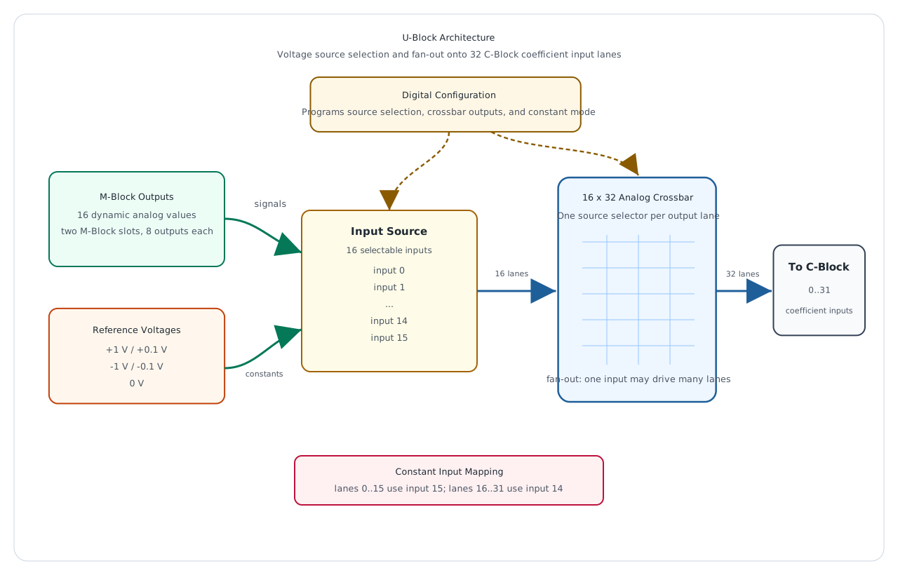
The U-Block is the voltage distribution block inside a cluster. Its name follows the physical symbol U for voltage. The block takes analog source voltages from the cluster, optionally substitutes calibrated reference voltages, and distributes the selected voltage sources onto the 32 coefficient input lanes of the C-Block.
In the signal chain, the U-Block is the main fan-out stage between produced analog values and the coefficient network used by downstream blocks. In a closed-loop configuration, its normal dynamic inputs are the output voltages produced by the two M-Block slots in the cluster. The U-Block can also inject fixed voltages, which are used for constants, offsets, and reference terms in analog programs.
Role in the Cluster
The U-Block receives 16 selectable analog input channels and drives 32 output lanes. These 32 lanes feed the 32 C-Block coefficient channels. Each output lane is programmed independently. For every output lane, the U-Block chooses one of the 16 available input channels or leaves the lane disconnected.
Because the block routes voltage signals, one selected input may be distributed to multiple output lanes at the same time. This fan-out behavior is essential for analog computing circuits: the same state variable, multiplier output, or constant can be reused by several coefficient inputs without consuming additional source hardware.
The U-Block does not apply the coefficient itself. It decides which voltage is presented to each coefficient input. The following C-Block channel then applies the programmed scalar factor for that lane.
Signal Sources
Each U-Block input position can represent one of the available source categories selected by the surrounding input multiplexing:
- A signal from the M-Block output path. A cluster can provide 16 dynamic M-Block output signals through its two M-Block slots.
- A positive reference voltage, selected as either
+1 Vor+0.1 V. - A negative reference voltage, selected as either
-1 Vor-0.1 V. - The
0 Vreference.
The reference-voltage path provides the constant values used by the analog program. The magnitude can be switched between the full-scale 1 V range and the smaller 0.1 V range, while polarity is selected by choosing the positive or negative reference source. The zero reference provides an explicit grounded source for lanes that should carry no signal but still be driven by a defined voltage.
This source selection is what gives the downstream C-Block and T-Block routing flexibility. For example, if a routed lane uses C-Block bit 17, the U-Block can still freely choose which M-Block output or reference voltage is weighted by C-Block channel 17 before that bit is used locally or shared through the routing fabric.
Crossbar Structure
The core of the U-Block is a 16 x 32 analog crossbar:
- The 16 crossbar inputs are the selectable voltage sources.
- The 32 crossbar outputs are the C-Block coefficient input lanes.
- Each output lane stores one selected source index.
- A source can be used by any number of output lanes.
- An output lane can be disabled when no source should be connected.
Conceptually, the U-Block behaves as 32 independent selectors. Each selector chooses one of the 16 input voltages and forwards it to its output lane. This makes the block different from a simple one-to-one switch matrix: it is optimized for distributing a smaller set of analog source voltages across a wider internal lane bus.
Constants
The U-Block supports the following constant values:
+1.0-1.0+0.1-0.10
In pybrid, constant mode controls the reference source that is made available on the reserved constant input positions. The two halves of the output-lane range use different reserved source inputs:
- Output lanes
0..15use source input15for constants. - Output lanes
16..31use source input14for constants.
This split follows the internal crossbar implementation. User code normally does not need to handle the hardware detail directly; it can enable the desired constant and connect the appropriate reserved source input to the required lane.
Example Signal Flow
A typical dynamic signal route through the U-Block follows this path:
- The M-Block has an analog output voltage inside the cluster.
- The U-Block input-source selection makes that voltage available as one of the 16 crossbar inputs.
- The U-Block crossbar is programmed so one or more output lanes select that source input.
- The selected voltage is distributed onto the configured C-Block coefficient input lanes in the
0..31lane range. - The C-Block scales the selected voltage on each lane before the result is routed further.
A typical constant-voltage route follows this path:
- The required constant value is selected from
+1.0,-1.0,+0.1,-0.1, or0. - Constant mode makes the selected reference voltage available on the reserved constant input for the relevant output-lane half.
- For output lanes
0..15, the lane is connected to source input15. - For output lanes
16..31, the lane is connected to source input14. - The selected constant voltage is then driven onto the configured output lane.
A typical fan-out route follows this path:
- One source input is selected, either from the M-Block signal path or from the reference-voltage path.
- Multiple output lanes are configured to select the same source input.
- The U-Block distributes the same voltage to all selected C-Block coefficient inputs at the same time.
- Each selected lane can then use a different C-Block coefficient, so the same source voltage can create multiple differently weighted contributions.
A typical shareable-lane route follows this path:
- A lane in the
8..31range is chosen because it can participate in the T-Block routing fabric. - The U-Block assigns the desired M-Block output or constant source to that lane.
- The C-Block applies the coefficient for the same lane index.
- The T-Block can then select the weighted lane for same-cluster use, another cluster, or the backplane.
Programming with pybrid
The U-Block is available on a cluster as cluster.ublock.
Reset the U-Block
reset() disconnects all 32 output lanes and disables constant mode.
Route a Source to One or More Output Lanes
input is the selected source index in the 0..15 input range. output is the destination C-Block coefficient lane in the 0..31 output-lane range.
For example, this routes source input 4 to output lane 16:
The same source can be routed to several lanes:
By default, pybrid protects an already configured output lane from accidental overwrite. Use force=True only when replacing an existing route intentionally:
Configure a Constant
cluster.ublock.set_constant(+1.0)
cluster.ublock.set_constant(-1.0)
cluster.ublock.set_constant(+0.1)
cluster.ublock.set_constant(-0.1)
cluster.ublock.set_constant(0)
set_constant() selects the constant voltage made available to the U-Block constant inputs. Passing False or resetting the block disables constant mode. Passing True is equivalent to selecting +1.0.
After selecting the constant, connect the reserved constant source for the output-lane half being used:
# Constant on a lower-half output lane.
cluster.ublock.set_constant(+1.0)
cluster.ublock.connect(15, 0)

# Constant on an upper-half output lane.
cluster.ublock.set_constant(+1.0)
cluster.ublock.connect(14, 16)
Configuration Model
In pybrid, the U-Block configuration is represented by two fields:
outputs: a list with 32 entries. Each entry is eitherNonefor a disconnected lane or an input index selecting one of the 16 source inputs.constant: the enabled constant value, orFalsewhen constant mode is disabled.
This model mirrors the hardware behavior: every C-Block coefficient input lane is independently assigned to one selected voltage source, while the reference-voltage selection is configured separately.