T-Block BPL
The T-Block BPL is used where the topology decision must be made inside the backplane instead of on a local front-facing T-Block. A standard T-Block routes between the C-Block, I-Block, and backplane of one mREDAC. The T-Block BPL is installed in the backplane path and provides the routing point that connects mREDAC positions and the neighboring iREDAC assemblies.
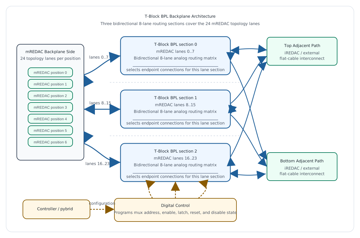
In the backplane implementation, the T-Block BPL is not used as one single 24-lane block. The backplane uses three identical T-Block BPL routing sectors. Each sector handles eight lane numbers for all connected mREDAC positions. Together, the three sectors form the 24-lane routed topology path for the mREDAC backplane.
Backplane sectors
| BPL sector | Backplane offset lanes | mREDAC routed lanes | Role |
|---|---|---|---|
| sector 0 | 0..7 |
8..15 |
Routes the first 8-lane sector for every mREDAC and adjacent path. |
| sector 1 | 8..15 |
16..23 |
Routes the second 8-lane sector for every mREDAC and adjacent path. |
| sector 2 | 16..23 |
24..31 |
Routes the third 8-lane sector for every mREDAC and adjacent path. |
This sector structure is important for understanding the backplane. The BPL sectors use backplane offset lanes 0..23, which correspond to mREDAC routed lanes 8..31 after subtracting the local T-Block offset of 8. For example, mREDAC lane 13 becomes backplane offset lane 5 and belongs to sector 0; mREDAC lane 20 becomes offset lane 12 and belongs to sector 1; mREDAC lane 28 becomes offset lane 20 and belongs to sector 2.
Each sector has the same architectural role. It receives the relevant eight topology lanes from the connected mREDAC positions, makes the routing decision for those lanes, and connects the selected lane paths to other mREDAC positions or to the adjacent iREDAC/external paths.
Signal Architecture
The functional signal path consists of three main parts:
- The backplane DIMM sockets wiring maps mREDAC input and output lane groups into one of the three T-Block BPL sectors.
- The analog signal matrix inside each sector uses repeated 8-channel analog multiplexer sectors.
- The adjacent iREDACs extend the same routing matrix beyond the local mREDAC backplane positions through the flat-cable interconnects.
The signal flow is bidirectional at the architecture level. A routed lane can be considered as a connection between endpoints rather than a permanently fixed source to destination wire. Depending on the configured topology, an mREDAC lane may be connected to another mREDAC lane, or to one of the adjacent iREDACs. The selected route defines which endpoints are connected for that lane.
Routing Model
At the backplane level, the T-Block BPL system is a 24-lane routing element made from three 8-lane sectors. Each lane belongs to the same logical lane number on each connected mREDAC and adjacent iREDACs. The route configuration selects which endpoints are connected for that lane.
For mREDAC-to-mREDAC routing, the appropriate T-Block BPL sector connects the selected lane between two mREDAC positions through the backplane. The connection is made on the corresponding lane number inside the selected 8-lane sector.
For mREDAC-to-adjacent-iREDAC routing, the same sector connects the selected lane to the flat-cable path. In this role, the T-Block BPL sector acts as a bridge between the horizontal mREDAC backplane lanes and the vertical iREDAC-to-iREDAC interconnect.
The available route endpoints for a signal are therefore:
- Another mREDAC on the same backplane segment.
- The adjacent iREDAC path connected through the top flat cable.
- The adjacent iREDAC path connected through the bottom flat cable.
Important
- Avoid routes where the source and destination are the same endpoint; higher-level routing or caller code must enforce this when using low-level BPL calls.
- Similar to the T-Block, T-Block BPL maintains the same lane number throughout. There is no option to switch between lane numbers in T-Block BPL.
Control Architecture
The routing matrix is controlled digitally. The control path uses serial configuration logic, latching, buffering, and mux-enable signals to program the analog muxes.
Important control behavior:
- The control data is shifted into the board through an SPI interface.
- SPI Mode 0 is expected for the shift-register controlling the muxes.
- The most significant bit is pushed first when loading the control chain.
- A latch transfers the shifted data into the active mux-control outputs.
- A reset path is provided for the control chain.
- A mux-disable function allows the matrix to be disabled while control state is being changed.
This means the routing state is not changed by rewiring the analog lanes directly. Instead, software programs the digital control chain, the control state holds the selected mux addresses and enables, and the analog mux matrix applies the selected signal routes. In the full backplane, this programming model applies to the three 8-lane BPL sectors that together implement the 24-lane route set.
Example Signal Flow
A typical mREDAC-to-mREDAC route follows this path:
- A route is requested for one of the 24 mREDAC routed lanes,
8..31. - The mREDAC lane is converted to a backplane offset lane by subtracting
8. - The offset lane selects the matching BPL sector:
0..7,8..15, or16..23. - The selected sector connects the lane between two different mREDAC positions.
- The programmed mux address and enable signals define the active endpoint connection.
- The signal can then pass through the selected lane path between the connected endpoints.
A typical mREDAC-to-adjacent-iREDAC route follows this path:
- A route is requested for one of the 24 mREDAC routed lanes,
8..31. - The corresponding T-Block BPL sector receives the backplane offset lane selection.
- The analog mux matrix connects the lane to the top or bottom adjacent iREDAC/external path.
- The signal passes through the flat-cable interconnect between the backplane and the adjacent path.
Programming with pybrid
In pybrid, the three T-Block BPL sectors on a backplane are exposed on the carrier as st0block, st1block, and st2block. These names correspond to the three 8-lane sectors:
pybrid block |
Backplane offset lanes | mREDAC routed lanes | Local lane inside the sector |
|---|---|---|---|
st0block |
0..7 |
8..15 |
backplane_lane % 8 |
st1block |
8..15 |
16..23 |
backplane_lane % 8 |
st2block |
16..23 |
24..31 |
backplane_lane % 8 |
The functional calls to connect are:
carrier.st0block.connect(src_sector, dst_sector, sector_lane)
carrier.st1block.connect(src_sector, dst_sector, sector_lane)
carrier.st2block.connect(src_sector, dst_sector, sector_lane)
connect(src_sector, dst_sector, sector_lane) configures one lane inside one BPL sector. src_sector selects the endpoint that provides the signal, dst_sector selects the endpoint that receives the selected signal, and sector_lane is the lane number inside the 8-lane sector.
The current source selection for a destination can be read back with:
The same source(dst_sector, sector_lane) call is available on st1block and st2block. A BPL sector can also be cleared with:
The same reset() call is available on the other two sectors.
For a route using the global mREDAC routed lane number, subtract the local T-Block offset first, then select the BPL sector and local 8-lane index:
mredac_lane = 20
backplane_lane = mredac_lane - 8
sector_index = backplane_lane // 8
sector_lane = backplane_lane % 8

bpl = [carrier.st0block, carrier.st1block, carrier.st2block][sector_index]
bpl.connect(src_sector, dst_sector, sector_lane)
From the hardware point of view, each programmed route must define four things:
- The source connector or source mREDAC position.
- The mREDAC routed lane number, from
8to31. - The backplane offset lane, from
0to23, selected bymredac_lane - 8. - The BPL sector selected by that offset lane:
st0block,st1block, orst2block. - The destination connector, which may be another mREDAC position, the top adjacent iREDAC/external path, or the bottom adjacent iREDAC/external path.
The hardware/topology should avoid routes where the source and destination are the same connector. Higher-level routing or caller code must enforce this when using the low-level BackplaneTBlock.connect(...) API.
At hardware-control level, a safe update sequence disables the affected mux paths, shifts the new mux-control data, latches the shifted state, and re-enables the required paths. The current low-level public pybrid BPL API exposes the configuration model rather than that latch/disable sequence:
carrier.st0block.connect(src_sector, dst_sector, sector_lane)
carrier.st0block.source(dst_sector, sector_lane)
carrier.st0block.reset()
The software interface should preserve the three-sector lane mapping and the different-endpoint routing assumption.
Design Notes
- A single T-Block BPL instance is an 8-lane sector in the REDAC backplane architecture.
- The complete mREDAC topology lane set is formed by three T-Block BPL instances.
- The T-Block BPL is a routing module, not a signal-conditioning module. The documentation should not be read as adding amplification, conversion, or termination behavior unless those functions are explicitly part of the hardware design.
- The board depends on both analog routing and digital control. A correct route requires both a valid signal path and a valid mux-control state.
- The adjacent flat-cable paths are part of the routed topology path and should be treated as destinations equivalent to adjacent iREDAC/external positions.
- The repeated mux structure keeps the lane behavior consistent across each 8-lane sector.